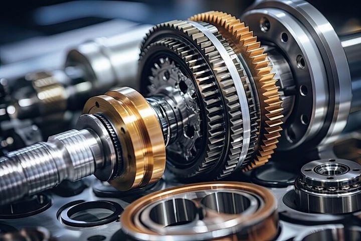
Gearboxes Guide: Explore Types, Components, Gear Ratios, Applications, and Selection Factors
A gearbox is a mechanical device used to transmit power between a driving source and a driven machine while changing speed, torque, or direction. Gearboxes are found in vehicles, industrial machinery, conveyors, elevators, robotics, agricultural equipment, wind turbines, and many other mechanical systems. Understanding gearboxes involves looking at their types, components, gear ratios, applications, and selection factors.
The basic idea behind a gearbox is based on gears working together at different sizes and speeds. When one gear drives another, the relationship between their teeth affects rotational speed and torque. By combining gears in different arrangements, a gearbox can adapt the motion produced by a motor or engine to the requirements of another machine.
Early mechanical transmission systems used simple gear arrangements to transfer rotary motion. Over time, engineering developments introduced more compact and specialized designs, including spur, helical, bevel, worm, planetary, and other gearbox configurations.
Today, gearboxes range from small precision units used in instruments and robotics to large industrial systems designed to transmit substantial mechanical power. Although their designs differ, their central purpose remains the controlled transmission of rotary motion.
How a Gearbox Works
A basic gearbox contains gears mounted on shafts. One shaft receives rotational input, while another shaft transfers the modified rotation to the driven equipment.
If the output gear is larger than the input gear, output speed generally decreases while available torque increases, assuming other losses are excluded. If the output gear is smaller, output speed generally increases while torque decreases.
The relationship can be expressed through a gear ratio. For a simple gear pair:
Gear ratio = Number of teeth on driven gear ÷ Number of teeth on driving gear
For example, a driving gear with 20 teeth connected to a driven gear with 60 teeth produces a 3:1 ratio. The driven gear rotates at approximately one-third of the driving gear's speed, while its theoretical torque multiplication is approximately three times before losses are considered.
Main Gearbox Types
Different gearbox designs are suited to different motion and power requirements.
- Spur gearboxes use straight-cut teeth and have a relatively simple arrangement.
- Helical gearboxes use angled teeth that provide gradual tooth engagement.
- Bevel gearboxes transfer motion between intersecting shafts, often at an angle.
- Worm gearboxes use a worm and wheel arrangement and are commonly used where large speed reduction is needed.
- Planetary gearboxes use a sun gear, planet gears, and a ring gear in a compact arrangement.
- Hypoid gearboxes use offset bevel-type gearing and are commonly associated with vehicle drivetrains.
- Rack-and-pinion systems convert rotary motion into linear motion rather than producing conventional rotary output.
The appropriate design depends on speed, torque, space, shaft arrangement, efficiency requirements, operating conditions, and other system characteristics.
Importance
Gearboxes are important because motors and engines do not always produce motion in the form required by the machine they drive. A motor may rotate too quickly, while the driven equipment may require slower movement with greater torque.
A gearbox provides a mechanical way to match these different requirements. It can also change the direction of rotation or transfer motion between shafts positioned at different angles.
Why Gear Ratios Matter
Gear ratio is one of the central concepts in gearbox operation. A reduction ratio allows the output shaft to rotate more slowly than the input shaft while increasing available torque relative to the input.
For example, consider a motor rotating at 1,800 revolutions per minute (RPM) connected to a gearbox with a 6:1 reduction ratio:
Output speed = 1,800 ÷ 6 = 300 RPM
This simplified calculation does not account for slip because gears operate through mechanical engagement, but real systems experience efficiency losses that affect actual output torque and power.
A higher reduction ratio can provide greater torque multiplication but generally produces lower output speed. Selecting the ratio therefore requires an understanding of the driven machine's operating requirements.
Common Gearbox Components
A typical gearbox may contain several mechanical and structural components:
- Gears transmit rotational motion and torque.
- Shafts support gears and transfer rotation.
- Bearings support rotating shafts and help control friction.
- Housing contains and protects internal components.
- Seals help retain lubricant and limit contamination.
- Lubricant reduces friction and helps manage heat.
- Couplings may connect the gearbox to a motor or driven machine.
- Keys, splines, or other connection methods transfer torque between shafts and mounted components.
The exact arrangement varies significantly between gearbox types.
Applications Across Industries
Gearboxes are used in many mechanical systems. Examples include:
| Application | Typical gearbox purpose |
|---|---|
| Conveyor systems | Reduce motor speed and increase output torque |
| Automobiles | Provide different speed and torque conditions |
| Elevators | Control lifting motion and mechanical output |
| Robotics | Provide controlled speed and torque |
| Wind turbines | Increase rotational speed from the turbine rotor |
| Agricultural equipment | Transfer and modify mechanical power |
| Industrial mixers | Provide controlled low-speed rotation |
| Packaging machinery | Coordinate mechanical movement |
| Cranes | Control lifting and movement mechanisms |
| Machine tools | Adjust spindle or feed motion |
The gearbox configuration changes according to the application. A conveyor gearbox, for example, may prioritize continuous operation and controlled output speed, while a robotic gearbox may emphasize precision, compactness, and low backlash.
Recent Updates
From 2024 through 2026, gearbox development has continued alongside broader trends in automation, electrification, robotics, renewable energy, and condition monitoring. Modern gearbox systems increasingly incorporate improved materials, manufacturing methods, lubrication technologies, sensors, and digital monitoring.
Automation and Robotics
Industrial robots require controlled movement across multiple axes. Gearboxes used in robotic joints must provide suitable torque, speed, positioning behavior, and compact dimensions.
Precision gearbox designs such as planetary and harmonic-type transmission systems are used in applications where controlled movement and low backlash are important. The selection depends on the robot's payload, speed, accuracy requirements, and mechanical design.
Condition Monitoring
Digital monitoring has become increasingly relevant for industrial gearboxes. Sensors can measure parameters such as vibration, temperature, rotational speed, and lubricant condition.
These measurements can help identify changes in operating behavior. Condition monitoring is often integrated with broader industrial maintenance and asset-management systems.
Electrification
The expansion of electric vehicles and electrically driven industrial equipment has increased attention toward compact transmission systems designed around electric motors. Electric motors often operate across different speed ranges from traditional mechanical engines, influencing gearbox design and transmission requirements.
Renewable Energy
Wind turbines use specialized gearboxes in many drivetrain configurations to transfer rotational energy from large turbine blades to generators. Because wind turbines operate under changing loads and environmental conditions, gearbox design and monitoring remain important engineering considerations.
Laws or Policies
Gearbox requirements can be influenced by machinery safety rules, workplace regulations, electrical equipment requirements, environmental regulations, and technical standards. The exact requirements depend on the machine, industry, location, and application.
In India, workplace machinery safety is addressed through occupational safety legislation and related rules. The Occupational Safety, Health and Working Conditions Code provides a broader framework covering occupational safety and working conditions, while applicable state rules and sector-specific requirements may also apply.
The Bureau of Indian Standards (BIS) develops Indian Standards covering many areas of mechanical engineering, machinery, industrial equipment, and safety. Depending on the gearbox application, relevant standards may address dimensions, terminology, testing, materials, safety, or performance.
For industrial installations, gearbox selection and operation may also need to consider applicable electrical, environmental, noise, guarding, and workplace requirements. Specific compliance obligations should be assessed according to the complete machine rather than the gearbox alone.
Tools and Resources
Several resources can help explain gearbox design and selection.
Gear Ratio Calculators
A gear ratio calculator can determine relationships between gear teeth, input speed, output speed, and reduction ratios. Basic calculations can often be performed using:
Output RPM = Input RPM ÷ Gear Ratio
For multiple gear stages, the overall ratio is calculated by multiplying the individual stage ratios.
Torque and Power Calculations
Power, torque, and rotational speed are closely related. A commonly used relationship is:
Power = Torque × Angular Speed
Engineering calculations may use different units and conversion factors. More detailed gearbox selection requires consideration of efficiency, service conditions, starting loads, shock loads, and operating cycles.
Manufacturer Technical Manuals
Technical manuals provide information about gearbox dimensions, shaft arrangements, permissible loads, lubrication requirements, operating temperatures, mounting positions, and maintenance procedures.
These documents are useful because gearbox specifications vary significantly between designs.
Standards and Engineering References
BIS publications, international engineering standards, technical textbooks, and mechanical design references can provide additional information about gears, transmissions, safety, testing, and terminology.
A selection worksheet can also be useful for organizing the main requirements:
| Selection factor | Information to evaluate |
| Input speed | Motor or engine RPM |
| Required output speed | Desired driven-machine RPM |
| Torque | Required output torque |
| Ratio | Required speed reduction or increase |
| Power | Mechanical power transmitted |
| Shaft arrangement | Parallel, intersecting, or offset |
| Operating cycle | Continuous, intermittent, or variable |
| Load characteristics | Steady, variable, or shock loading |
| Environment | Temperature, dust, moisture, or chemicals |
| Mounting | Foot, flange, shaft, or other arrangement |
FAQs
What is a gearbox?
A gearbox is a mechanical transmission device that uses gears to transfer rotary power while changing speed, torque, or direction. It can connect a motor or engine to equipment requiring a different operating speed.
How does a gearbox ratio affect output speed?
A reduction gearbox decreases output speed according to its ratio. For example, with a 5:1 reduction and an input speed of 1,500 RPM, the simplified output speed is approximately 300 RPM.
What are the main types of gearboxes?
Common types include spur, helical, bevel, worm, planetary, and hypoid gearboxes. Each design has different characteristics related to speed, torque, shaft arrangement, efficiency, size, and application.
How do you select a gearbox?
Gearbox selection generally considers input speed, output speed, required torque, transmitted power, gear ratio, shaft arrangement, operating cycle, load characteristics, mounting configuration, environmental conditions, and space limitations.
What are the main components of a gearbox?
The primary components normally include gears, shafts, bearings, housing, seals, and lubricant. Depending on the design, a gearbox may also include couplings, keys, clutches, brakes, cooling systems, and monitoring sensors.
Conclusion
Gearboxes transfer mechanical power while adapting speed, torque, and sometimes the direction of rotation to suit a driven system. Different gearbox types use different gear arrangements, making them suitable for applications ranging from conveyors and vehicles to robotics and renewable-energy equipment. Gear ratio, torque, speed, power, shaft arrangement, operating conditions, and mounting requirements are important factors in understanding gearbox selection. Recent developments increasingly connect gearbox technology with automation, electrification, condition monitoring, and digital manufacturing.